
Earthworks terminology: essential guide for NZ projects
- Jay Price
- Mar 12
- 8 min read

Misunderstood earthworks terminology causes costly delays and safety risks on civil projects across New Zealand. When project teams struggle to communicate about excavation depth, ground stability or compaction specifications, the consequences extend beyond confusion to affect safety outcomes and compliance. This guide clarifies essential earthworks terms and best practices, equipping you with the knowledge to plan safer, more efficient civil projects that meet NZ standards.
Table of Contents
Key takeaways
Point | Details |
Clear terminology prevents costly project delays | Precise earthworks language improves communication between teams and reduces safety incidents. |
Site-specific assessments are mandatory | Ground condition evaluation identifies hazards before excavation begins and guides stability measures. |
NZ standards define testing protocols | NZS 4407:2015 specifies density measurement methods that ensure quality earthworks construction. |
Systematic hazard management is critical | Proper planning involves identifying risks, monitoring slopes and coordinating control measures across parties. |
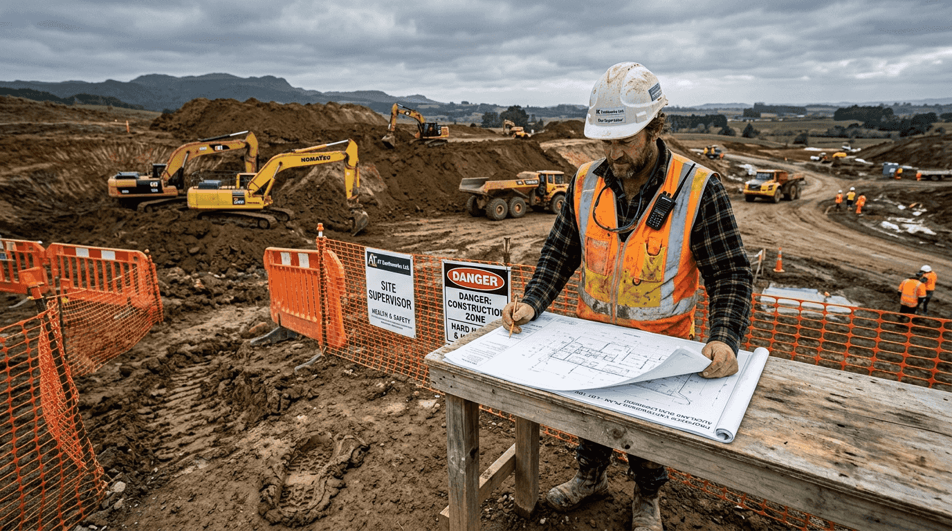
Understanding earthworks terminology and site conditions
Mastering fundamental earthworks terminology forms the foundation for successful project delivery. Excavation refers to the removal of earth material to achieve design levels, while ground instability describes conditions where soil or rock may move unexpectedly, threatening worker safety and structural integrity. A geotechnical assessment evaluates subsurface conditions through testing and analysis, identifying potential hazards before construction begins.
Site-specific ground condition evaluation cannot be skipped or generalised. Every location presents unique soil types, groundwater levels and geological features that directly impact excavation methods and stability requirements. Before any excavation begins, the responsible person should carry out an appraisal to identify principal hazards, including ground instability, with geotechnical assessment if needed.
Proper site preparation essentials include systematic hazard identification steps:
Review historical site records and geological maps for known instability indicators
Conduct visual inspections to identify surface cracks, seepage or vegetation patterns suggesting subsurface issues
Engage qualified geotechnical engineers when ground conditions appear complex or uncertain
Establish baseline monitoring protocols before excavation disturbs existing ground conditions
Best practices for controlling ground instability include regular slope monitoring using surveying equipment, excavation scaling to remove loose material before it falls, and implementing drainage systems that prevent water accumulation within slopes. These measures work together to maintain safe working conditions throughout the project lifecycle.
Core testing standards and soil density measurement methods
New Zealand’s soil density testing framework relies on NZS 4407:2015, which defines standardised procedures ensuring consistent quality across earthworks projects. Understanding these testing methods helps you specify appropriate quality control measures and interpret test results accurately during construction.
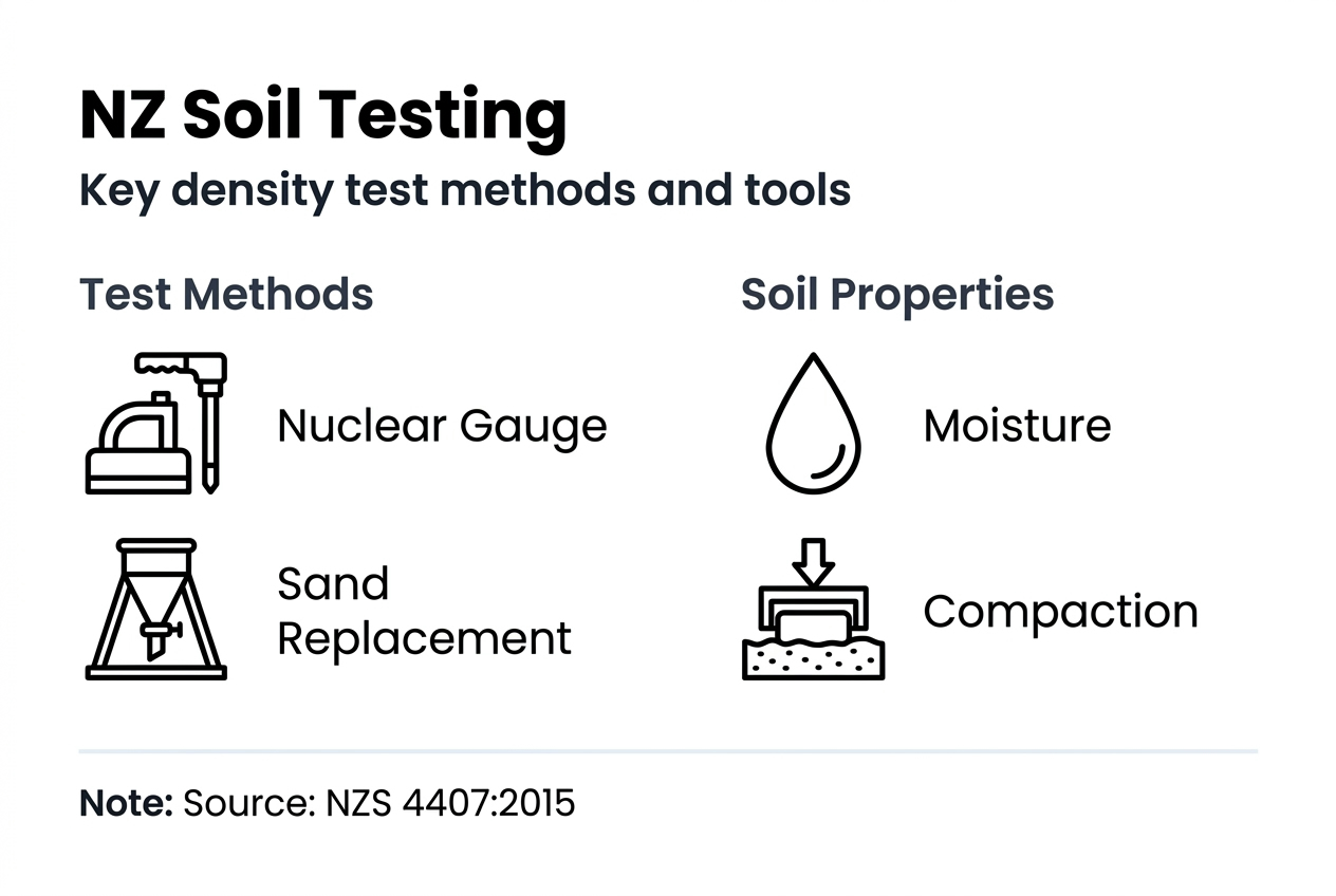
The full-depth direct transmission test (NZS 4407:2015 Test 4.2) provides a more accurate density measure when the layer thickness is ≥ 100mm. This method transmits gamma radiation through the full compacted layer depth, measuring actual in-place density against specified requirements. Backscatter mode (NZS 4407:2015 Test 4.3) measures bulk density to about 70 to 90mm depth, with moisture sensor approximately 75mm depth, making it suitable for thinner layers or surface verification.
Conducting accurate Plateau Density Tests requires following these steps:
Prepare a smooth, level test surface free from loose material or surface irregularities that could affect readings
Calibrate nuclear density gauge according to manufacturer specifications and regulatory requirements
Take multiple readings across the test area to establish representative density values
Record moisture content simultaneously, as density specifications typically reference a moisture-density relationship
Compare results against project specifications and adjust compaction methods if readings fall below requirements
Test Method | Measurement Depth | Best Application | Accuracy Level |
Full-depth direct transmission | Full layer ≥100mm | Thick layers requiring precise density | High |
Backscatter mode | 70 to 90mm | Thin layers or surface verification | Moderate |
Sand replacement | Variable | Calibration reference | High |
Choosing suitable testing conditions ensures reliable results. Surface moisture affects nuclear gauge readings, so testing immediately after rainfall may produce inaccurate measurements. Layer thickness must match the selected test method, as using backscatter mode on thick layers underestimates actual density. Temperature extremes can affect equipment calibration, requiring adjustments to maintain accuracy.
Pro Tip: Combining smooth drum and padfoot rollers in sequence often achieves optimal compaction results. The padfoot roller breaks up the material and increases density in deeper layers, while the smooth drum provides final surface compaction and seals the layer against moisture infiltration.
Managing ground instability and debris flow risks
Systematic ground instability management protects workers and preserves project integrity throughout earthworks operations. A systematic approach to managing ground instability is very important, requiring planned interventions rather than reactive responses to visible problems.
Practical steps for preventing and controlling instability include:
Identify potential failure modes through geotechnical analysis before excavation begins
Implement slope scaling procedures that remove loose material systematically from top to bottom
Establish monitoring protocols using survey equipment to detect ground movement before failure occurs
Install drainage measures that intercept groundwater before it destabilises slopes
Restrict access to high-risk areas through clear exclusion zones and worker briefings
Debris flow risks represent a specific instability hazard in earthworks, particularly on sloping sites with loose, saturated material. Unit 6 of the Slope Stability Geotechnical Guidance Series focuses on debris flow assessment, analyses and mitigation, providing technical frameworks for evaluating susceptibility and designing protective measures.
Mitigation strategies for debris flow hazards combine engineering controls with operational planning. Engineering controls include constructing debris barriers or deflection structures that redirect flows away from work areas, and establishing drainage systems that prevent water accumulation in vulnerable zones. Operational planning involves scheduling high-risk excavation activities during dry periods, maintaining emergency response procedures and training workers to recognise debris flow warning signs.
“Effective ground instability management requires coordination between geotechnical engineers, site supervisors and equipment operators. Each party contributes essential expertise to identify hazards, implement controls and monitor changing conditions throughout the project.”
Multi-party coordination ensures hazard control measures function as intended. Geotechnical engineers define stability requirements based on site-specific analysis. Site supervisors translate technical recommendations into practical work procedures that equipment operators can implement safely. Regular communication between these parties allows rapid adjustments when ground conditions differ from initial assessments, maintaining safety without halting progress unnecessarily.
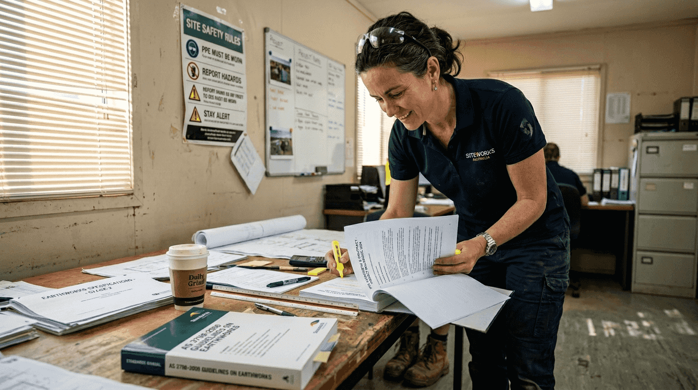
Key terminology in civil earthworks projects and contract specifications
Contract and specification terminology requires precise understanding to avoid costly misinterpretations during project delivery. Rock armour refers to large, durable rock placed to protect structures from wave action or erosion, with specific grading and durability requirements. The ACS1330 Rock Armour specification defines material requirements for rock armour in coastal works and excludes core/filter rock per ACS510 Earthworks, establishing clear distinctions between material types.
Grading describes the size distribution of rock or aggregate particles, typically expressed as percentage passing various sieve sizes. Core materials provide structural mass within embankments or coastal structures, while filter materials prevent fine soil particles from migrating through coarser layers, maintaining long-term stability.
Contract Works Specification encompasses the technical requirements governing materials, construction methods and quality standards for a specific project. These specifications reference broader standards like NZS 4407 while adding project-specific requirements addressing unique site conditions or design intent. Understanding which specification clauses apply to each work element prevents disputes over scope and quality expectations.
Approval processes for state highway access require careful navigation. The PPM guide outlines approval requirements and key factors for state highway access from private property, relevant for managing earthworks project access. Factors include sight distance, traffic volumes, intersection geometry and safety considerations that influence whether access receives approval and under what conditions.
Material Type | Primary Function | Grading Requirements | Durability Standards |
Rock armour | Erosion protection | Large, uniform sizing per ACS1330 | High abrasion resistance |
Core rock | Structural mass | Broader size range per ACS510 | Moderate durability |
Filter material | Prevent particle migration | Specific gradation curves | Chemical stability |
Specification differences between rock armour and core materials affect procurement and placement methods. Rock armour demands larger, more durable stone with strict size tolerances, commanding premium pricing and requiring careful placement to achieve design geometry. Core materials accept broader size ranges and moderate durability, allowing more flexible sourcing and faster placement rates. Confusing these specifications leads to material rejection, project delays and cost overruns.
Key civil earthworks project terms also include compaction specifications expressed as percentage of maximum dry density, cut and fill quantities measured in cubic metres, and batters referring to sloped surfaces described by vertical to horizontal ratios. These terms appear throughout contract documents and daily site communications, requiring consistent understanding across project teams.
Pro Tip: Always reference the latest versions of NZ standards and specifications. Standards undergo regular updates reflecting new research and industry experience. Using outdated versions creates compliance issues and quality problems that emerge during construction or post-completion audits.
Partner with expert earthworks contractors in Auckland
Navigating earthworks terminology and technical requirements becomes simpler with experienced earthworks contractors Auckland guiding your project. Bromley Group brings decades of civil construction expertise to residential developments, commercial projects and infrastructure works across the Auckland region. Our team understands the nuances of NZ standards, having delivered hundreds of successful earthworks projects that meet compliance requirements while staying on schedule and within budget.
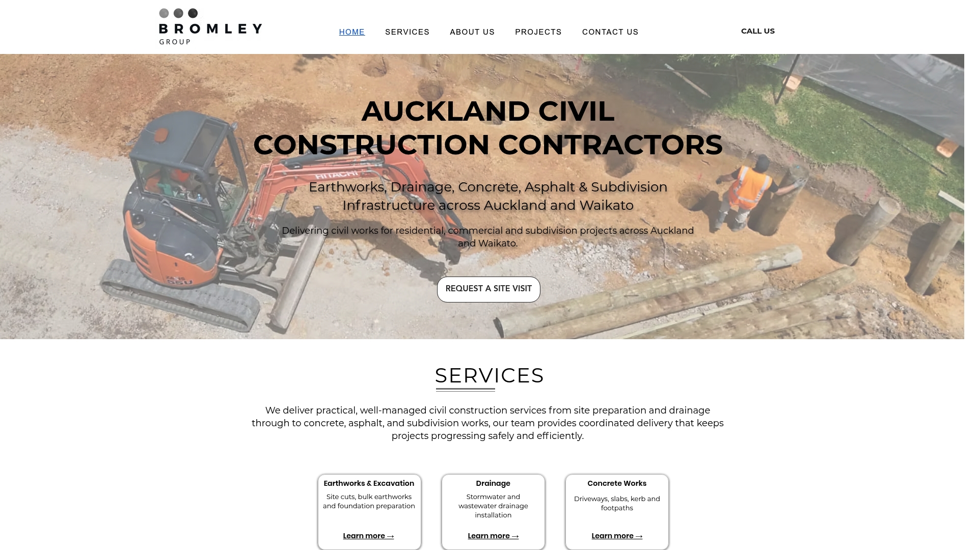
We specialise in subdivision civil contractors services including site cuts, bulk earthworks, drainage installation and concrete construction. Our project management approach ensures clear communication about technical requirements, test results and progress milestones, eliminating the confusion that derails projects. From initial geotechnical assessment through final compaction testing, we coordinate every aspect of earthworks delivery with precision and professionalism. Request a quote online to discuss your next civil project and discover how our expertise translates complex specifications into successful outcomes.
FAQ
What is geotechnical assessment in earthworks?
Geotechnical assessment evaluates subsurface soil and rock conditions through field testing and laboratory analysis, identifying characteristics that affect excavation safety and construction methods. A geotechnical assessment should be undertaken by a competent person when ground instability is identified as a principal hazard. This assessment informs design decisions about slope angles, support requirements and construction sequencing.
How do the NZS 4407:2015 tests differ in soil density measurement?
Full-depth direct transmission test measures density for layers ≥100mm, while backscatter mode measures bulk density to 70 to 90mm depth. Direct transmission provides higher accuracy for thick layers by measuring through the complete compacted depth. Backscatter suits thinner layers or quick surface verification but may not detect density variations in deeper portions of thick layers.
What are best practices for managing debris flow risks in earthworks?
Debris flow management begins with hazard identification through site assessment and historical data review. Debris flow assessment and mitigation follow detailed geotechnical guidance focusing on hazard analysis and management. Mitigation combines engineering controls like debris barriers with operational measures including work scheduling during favourable weather and establishing monitoring protocols that detect changing conditions before failure occurs.
Why does rock armour require different specifications than core materials?
Rock armour faces severe wave action and abrasion requiring superior durability and specific size distributions that dissipate energy effectively. Core materials provide structural mass without direct exposure to erosive forces, allowing broader gradations and moderate durability standards. These functional differences justify distinct specifications ensuring each material performs its intended role over the design life without premature degradation or failure.
How often should slope monitoring occur during earthworks?
Monitoring frequency depends on ground conditions, excavation depth and identified risk levels. High-risk slopes require daily monitoring using survey equipment to detect millimetre-scale movements indicating potential failure. Moderate-risk areas may require weekly monitoring, while stable excavations in competent ground need periodic verification. Increase monitoring frequency immediately after heavy rainfall or when excavation activities change slope geometry significantly.
Recommended